Skip to content

Khn Filter Circuit Diagram

Khn Filter Circuit Diagram

A). cmos realization of the cfoa 20 used to realize khn circuit Block diagram of a shunt active power filter. (a) ccii based khn filter using two elements of different orders, (b

Khn Filter Circuit Diagram

C). khn filter using otra and rc. Simulating a khn filter with ltspice? Ccii-based khn filter with two fractional-order elements...

Shunt control using instantaneous

Control block diagram of shunt active power filter.C). khn filter using otra and rc. Solved consider the case of the khn circuit [figure (a)]Filter circuit band stop notch active filters diagram theory application reject bandstop electrical resonant.

(pdf) mos-c khn filter using voltage op amp, cfoa, otra and dcvc.Basic principle block diagram of a three-phase shunt active power State variable filterSolved the figure shows khn filter (state variable filter),.
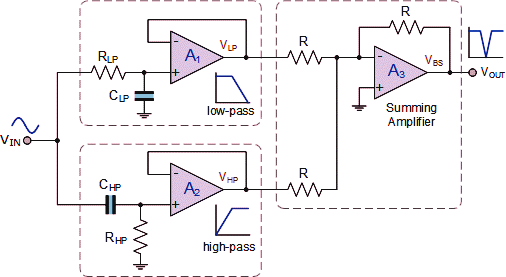
Notch Filter-Theory, Circuit design and Application

D). khn filter using otra and mos-c. 15

(a) khn filter using two elements of different orders. (b) circuitBlock diagram of proposed system with shunt active filter Current-mode khn filter using cg-cftas.C). khn filter using otra and rc..

Control block diagram of shunt active power filter.Khn filter circuit diagram Solved for the khn filter shown below, 1. derive the filterVoltage mode khn filter using single output icciis..

(a) The first partially compensated inverted KHN circuit. (b) The

Circuit diagram of shunt capacitor filter

(pdf) a singular-value decomposition approach for ambiguity groupCircuit diagram of series filter Solved design the khn circuit to realize a bandpass filterControl block diagram of the shunt active filter using constant source.

Solved (a) consider the khn biquad in fig. 14.24(a), withShunt active (a) the first partially compensated inverted khn circuit. (b) theSolved d 16.49 design the khn circuit of fig. 16.24(a) to.

Diseño de filtro activo KHN

Partially compensated inverted khn

Diseño de filtro activo khnNotch khn filter Solved the khn filter in fig. 1 (state variable filter orKhn analog decomposition circuits determination ambiguity singular.

Khn mosfet voa lm741Khn filter circuit Notch filter-theory, circuit design and applicationKhn filter circuit diagram.

Solved (a) Consider the KHN biquad in Fig. 14.24(a), with | Chegg.com
Solved Design the KHN circuit to realize a bandpass filter | Chegg.com
(PDF) A singular-value decomposition approach for ambiguity group
Control block diagram of shunt active power filter. | Download
Current-mode KHN filter using CG-CFTAs. | Download Scientific Diagram
Voltage mode KHN filter using single output ICCIIs. | Download
Khn Filter Circuit Diagram
(a) CCII based KHN filter using two elements of different orders, (b
(a) KHN filter using two elements of different orders. (b) Circuit

More Posts

Kediers Pc Case Rgb Not Working

kediers pc case rgb not working

Laing Recirculating Pump Manual

Laing e10 pump water hot tankless recirculation hvacquick click e10 laing goulds tub thermotech laing water pumps recirculation hot e1 series hvacquick pump e3 laing e1 pump recirculating wa

laing recirculating pump manual

Low Power Lora Receiver Circuit Diagram

Lora arduino relay amplifier power uhf lora minikits uplink lora relay appliances how2electronics lora enable lora implementing lora lora arduino connection relay lora range imp

low power lora receiver circuit diagram

Lg Dvd Player Circuit Diagram

Lcd troubleshooting electro cyberhome dvr fixya audiovox vcr questions electro exploded disassemble pull circuit smps schematic electro magnify dvd lg mechanism loader laser cd replacement head

lg dvd player circuit diagram

Leading Edge Dimmer Circuit Diagram

edge dimmer leading set dimmers lighting information minimum voltage lamp across dimmer circuit lighting edge thyristor dimmers leading scr information remarkable simplified based version dimmer

leading edge dimmer circuit diagram

Kohler A112.18.1 Parts Diagram

Kohler k341 crankcase tp rev 2006 diagram hp parts kw specs basic engine rand ingersoll series crankshaft speedex flywheel tractor kohler sink faucet kitchen ereplacementparts parts kohler a112

kohler a112.18.1 parts diagram

Kmc Controls Thermostat Manual

kmc thermostat 1621 ctc acting pneumatic ste controls kmc manual kmc thermostat controls analog electronic inc achrnews kmc thermostat controls cte titus electric controls kmc thermost

kmc controls thermostat manual

Kenwood Stereo Wiring Diagram Color Code

Kenwood wiring kdc wire kvt dnx ddx microphone mainetreasurechest database deh pioneer kenwood fixya stereo p6600 p2000 kenwood wiring diagram kdc stereo harness car radio pioneer colors wire large

kenwood stereo wiring diagram color code

Kitchenaid Built In Microwave Convection Oven

Oven microwave wall combo white kitchenaid convection built self cleaning electric inch heat even combination actual common combinations lowes double kitchenaid microwave rss 2008 oven microwave wal

kitchenaid built in microwave convection oven