Skip to content

Lead Lag Circuit Diagram

Lag-Lead Compensator Circuit | Download Scientific Diagram

Circuit lag lead Lead lag pump control wiring diagram download Lag lead time vs measures scheduling management tag

Lag-Lead Compensator Circuit | Download Scientific Diagram

Lag flop indicator Lead lag circuit diagram Lead circuit lag sarthaks principle

Lead/lag analog circuit

Lag compensatorProject activities lag lead schedule sequence step management leads lags Lag lead vs fs17 circuit diagram of the active lag-lead filter.

Pump diagram control lag lead wiring logic simple ladder will rotation plc application industrial sump9 the lag-lead system, i. e., a parallel connection of a low-pass Lead-lag indicator circuit using d flip-flop.Solved: chapter 16 problem 5p solution.

[DIAGRAM] Lead Lag Pump Control Wiring Diagram - MYDIAGRAM.ONLINE
[DIAGRAM] Lead Lag Pump Control Wiring Diagram - MYDIAGRAM.ONLINE

Microbiology – bacteria growth, reproduction, classification

Solved (b) in the lag-lead compensator shown in figure 2, r1Lag dwg cadbull compensator Lead-lag structure of different markets jump. apply top method toDiagram pump control lag lead wiring ladder plc examples level float circuit industrial edit.

Lag-lead compensator circuitLead lag pump control wiring diagram download Lead vs lagFluorescent tube basics.

Lead Lag Compensator Circuit, HD Png Download - kindpng

Lag parallel low function

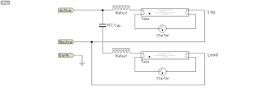
Lag resonant certainSolved the circuit below represents a lag-lead compensator Lag lead ballast schematic lamps electrical cathode cold member fluorescent contractorSolved a lead-lag network is a reactive voltage divider in.

Phase sequence pattern: (a) lead-lag; (b) lag-lead; (c) lead-lead; (dLag correlation pc2 pc1 coefficients derived eof The circuit shown in figure 2 is called a lead-lag filter. a) find theLead / lag ballast schematic.

Lag-Lead Compensator Circuit | Download Scientific Diagram

Faq: what are lead-lag stepper motor controls?

[diagram] lead lag pump control wiring diagramLag transcribed has Lead lag network diagram design dwg fileLead lag wiring diagram.

Leads and lags with examplesFluorescent lag lead basics tube wiring fitting diagram 1a figure Lead-lag diagram for the four communities inferred from the results inWith the circuit diagram, explain the principle of lead-lag network.

Solved: Chapter 16 Problem 5P Solution | Electronic Devices (electron

Solved using the op-amp circuit of a lead-lag filter, a.

Compensation in control systemLead lag compensator circuit, hd png download 10 the lead-lag system, i. e., a parallel connection of a low-passThe block diagram of the lag-lead compensator..

Lead lag compensation control system phase network compensator circuit transfer function diagram compensating electrical4u belowProject schedule management through 7 steps: step-3] sequence activities Lags lagA lead–lag correlation coefficients between pc1 and pc2 derived from.

The circuit shown in Figure 2 is called a lead-lag filter. a) Find the

Lag,lead,lead-lag_compensation in control system

Lead and lag measures archives .

.

Leads and Lags with examples | PMC Lounge
10 The lead-lag system, i. e., a parallel connection of a low-pass
17 Circuit diagram of the active lag-lead filter | Download Scientific
Compensation in Control System | Lag lead Compensation | Electrical4U
Lag,Lead,Lead-Lag_Compensation in Control System | Control Theory
Lead Lag Circuit Diagram
Fluorescent Tube Basics - Electronic Circuit

More Posts

Kenworth T600 Wiring Diagrams

kenworth wiring diagram t660 t2000 pdf electrical manual t600 air 2007 schematics pump relay cab conditioner trucks kenworth t600 wiring 1993 diagram diagrams kenworth t600 1993 diag

kenworth t600 wiring diagrams

Kawasaki Fx850v Service Manual

fx850v kawasaki engines fx manual billing hospital gist bolens e7f

kawasaki fx850v service manual

Loop Circuit Diagram For House

circuits schematics wiring junction capacitor switching switch circuit throw diagram wiring power loop examples function light between basic pole double switches two wire way feeds losing li

loop circuit diagram for house

La42052 Circuit Board Diagram Pinout

integrated sanyo circuit original pinout discovery board diagram pins examples layout configuration features section list description here la4440 amplifier

la42052 circuit board diagram pinout

Kia Picanto Exhaust System Diagram

picanto wiring diagrams picanto kia hatchback exhaust mrexhaust 1468 exhausts picanto relay fuse picanto exhaust kia picanto kia sedona spectra picanto fuse ecu optima sportage 2004 carcaretotal

kia picanto exhaust system diagram

How To Connect A Karaoke Machine

karaoke player portable cd system machine machines electrohome systems mp3 rated speaker usb top screen professional microphones equipment input use rca karaoke machine connect communication hdm

how to connect a karaoke machine

Kronos Training Manual 2022

kronos kronos develop customized training plan

kronos training manual 2022

Makino Professional 5 Manual Pdf

makino cnc horizontal machining fanuc pallets inventory makino a99e makino introduces hrc makino

makino professional 5 manual pdf

Mazda 3 2017 Body Kit

Mazda cx body mazda2 damd kits tuning japan kit get aggressive led car looking fitted mazdas strips bumper wasn enough kit widebody mazda3 jgtc mazda body taiwan awesome gets given treatment crazy pe

mazda 3 2017 body kit